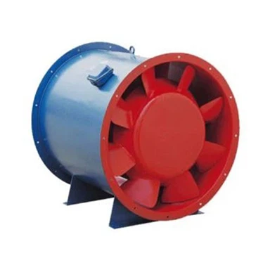
Why Does Fan Airflow Decrease After Installation?
Oct 01, 2026
A fan may meet its specified airflow during factory testing but deliver noticeably less air after it is installed in a factory ventilation or exhaust system. This situation can be confusing for buyers and maintenance teams, especially when the motor starts normally and the fan does not show any obvious mechanical damage.
In many cases, the problem is not that the fan has suddenly lost its capacity. The actual installation may create different airflow conditions from those used during fan selection or performance testing.
Incorrect duct connections, elbows installed too close to the inlet, excessive system resistance, low fan speed, incorrect rotation, and unsuitable damper settings can all reduce delivered airflow.
Before replacing the fan or increasing motor power, it is important to identify where the airflow is being lost. The following checks provide a practical troubleshooting sequence for industrial fan installations.
1. The Inlet or Outlet Ductwork Restricts Airflow
One of the first things to inspect is the ductwork connected to the fan.
A fan selected for a particular airflow and pressure operates according to its performance curve. If the installed duct system creates more resistance than expected, the actual operating point changes and the delivered airflow may decrease.
Common installation problems include:
Duct diameters smaller than those specified in the design.
Abrupt transitions between different duct sizes.
Partially blocked inlet or outlet sections.
Excessively long duct routes with unnecessary fittings.
Poorly designed branch connections.
Dampers that are not fully open.
For example, a centrifugal fan may be selected for a dust extraction system with a certain duct diameter. During installation, the contractor may reduce the duct size because of limited space. The smaller duct increases air velocity and friction losses, potentially pushing the fan away from its intended operating point.
What to check:
Compare the installed duct dimensions with the approved drawings. Inspect the complete airflow path, including transitions, branches, elbows, dampers, and filters.
Do not assume that the ductwork is correct simply because all connections can be physically assembled.
2. An Elbow Is Installed Too Close to the Fan Inlet
This is one of the most overlooked causes of reduced airflow after installation.
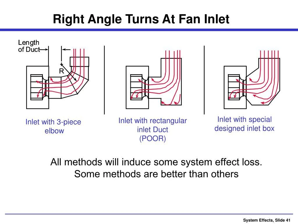
A centrifugal fan is designed to receive relatively uniform airflow at its inlet. When an elbow is installed immediately before the inlet, the air may enter the impeller unevenly or with unwanted swirl.
The resulting airflow disturbance is known as an installation system effect. It can reduce the fan's effective performance even when the fan itself is operating correctly.
The problem is particularly important when the inlet duct changes direction immediately before reaching the fan.
For example, an installation layout may require a 90-degree elbow directly beside the inlet because of limited factory space. Although the duct connection fits, the incoming air may not distribute evenly across the impeller.
What to check:
Inspect the inlet duct arrangement.
Look for elbows, tees, transitions, or obstructions close to the inlet.
Check whether the inlet opening has sufficient clearance.
Compare the actual arrangement with the manufacturer's recommended installation layout.
Where space permits, provide a suitable straight inlet section or redesign the connection to improve airflow distribution. The required arrangement depends on fan type and manufacturer's guidance; there is no single straight-duct length that applies to every installation.
3. The Fan Outlet Connection Creates Excessive System Effect
The outlet arrangement can also reduce the airflow delivered by an installed fan.
A fan may be tested under a particular outlet condition, but the actual installation may connect directly to a sharp elbow, abrupt expansion, or poorly designed discharge chamber.
These arrangements can prevent the airflow from developing properly after leaving the fan. The resulting pressure losses may be greater than those assumed during fan selection.
This problem is common when the fan is installed in a restricted equipment room or connected to existing ductwork that cannot easily be modified.
What to check:
Check whether an elbow is positioned immediately at the fan outlet.
Inspect abrupt changes in duct cross-section.
Look for obstructions and poorly arranged turning vanes.
Confirm that the discharge direction matches the fan's rotation and outlet arrangement.
Compare the installed outlet configuration with the manufacturer's performance test conditions.
For a centrifugal fan, an unsuitable discharge connection can create significant performance losses. Correcting the outlet arrangement may improve airflow without changing the fan or motor.
4. The Fan Rotates in the Wrong Direction
Incorrect rotation is another important installation-related cause of low airflow.
Many industrial centrifugal fans are designed to rotate in a specific direction. If the motor rotates in the opposite direction, the impeller may still turn and produce some airflow, but its performance can be substantially reduced.
This can happen after electrical installation, particularly when three-phase motor connections are changed.
The problem may not be obvious because the fan starts normally and the motor sounds as though it is running.
What to check:
Identify the correct rotation direction from the fan's rotation arrow or manufacturer's documentation.
Check the actual direction of rotation during a safe, controlled test.
Compare the observed direction with the specified direction.
If the direction is incorrect, have a qualified electrician correct the motor connections according to the electrical and equipment instructions.
Do not rely on airflow direction alone to judge whether a centrifugal impeller is rotating correctly. Verify the rotation against the manufacturer's marking.
Also distinguish incorrect motor rotation from an impeller that has been installed incorrectly. Both can reduce performance, but they require different corrective actions.
5. The Actual Fan Speed Is Lower Than the Design Speed
Even when the fan rotates in the correct direction, its speed may be lower than required.
This can occur because of an incorrect motor speed, unsuitable pulley ratio, loose or slipping belts, an incorrectly configured variable-frequency drive, or an incorrect speed setting.
For a belt-driven fan, the motor may operate normally while the fan shaft rotates more slowly than specified.
For a VFD-controlled fan, the operating frequency may have been set below the intended value during commissioning.
Lower rotational speed generally means lower airflow and pressure capability.
What to check:
Measure the actual fan shaft speed with a suitable tachometer.
Compare it with the fan selection and commissioning data.
Inspect belt condition and pulley sizes.
Check VFD frequency and control settings.
Verify that the motor and drive arrangement match the approved design.
Do not increase fan speed without checking the manufacturer's maximum allowable speed, motor current, impeller mechanical limits, and bearing operating conditions.
6. Filters, Dampers, and Other Components Increase System Resistance
The fan is only one part of an industrial ventilation system. Filters, dampers, silencers, heat exchangers, and other components also influence airflow.
If a filter is heavily loaded or a damper is partially closed, the system resistance may be higher than expected.
This is particularly relevant in dust collection systems, where filters can accumulate material during operation.
Another common installation problem is using a replacement filter with a higher pressure drop than the original design allowed for.
What to check:
Measure differential pressure across the filter.
Confirm that all dampers are in their intended positions.
Inspect silencers, coils, and other air-handling components.
Check for protective packaging or temporary covers left inside the airflow path.
Compare the measured pressure drop with the component manufacturer's data.
If the system has excessive resistance, correct the restriction rather than automatically increasing fan speed.
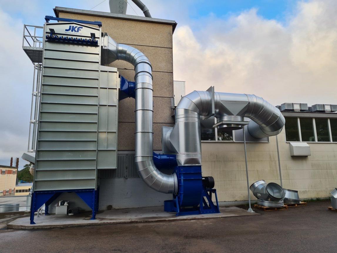
7. The Fan or Impeller Has Been Installed Incorrectly
Some airflow problems originate directly from the fan assembly.
During transportation, lifting, or installation, components may be damaged, displaced, or assembled incorrectly.
For centrifugal fans, important details include impeller orientation, inlet cone position, running clearance, and the relationship between the impeller and housing.
If the impeller is not correctly centered with the inlet cone, airflow into the wheel may be disturbed. Incorrect clearances can also affect performance and may create rubbing or mechanical damage.
Other possible issues include:
Impeller installed in the wrong orientation.
Incorrect blade angle where an adjustable-blade design is used.
Missing or incorrectly installed internal components.
Foreign objects or packaging material inside the housing.
Damage to the impeller during handling.
What to check:
After safely isolating the fan, inspect the internal assembly against the manufacturer's drawings and installation instructions.
If the impeller position, blade orientation, or internal clearance is uncertain, ask the manufacturer or a qualified service technician to verify the assembly before further operation.
8. Air Leaks in the Duct System Reduce Delivered Airflow
Duct leakage can also cause a difference between the airflow leaving the fan and the airflow reaching the intended working area.
In a supply-air system, leaks may allow air to escape before it reaches the target location.
In an exhaust system, leaks may draw unwanted air into the duct network, changing the airflow distribution and potentially reducing the amount of air captured at individual extraction points.
For example, a factory may install a central exhaust fan connected to several production stations. If one branch has poor sealing, the system may draw additional air through that leak rather than maintaining the required extraction at the intended collection point.
What to check:
Inspect duct joints, flange connections, access doors, and flexible connectors.
Check for damaged gaskets and loose clamps.
Conduct a suitable duct leakage test where necessary.
Measure airflow at individual branches rather than relying only on the fan outlet measurement.
If the fan outlet airflow is acceptable but the airflow at the working points is insufficient, investigate leakage and airflow distribution throughout the duct network.
9. Airflow Is Being Measured Incorrectly
Sometimes the fan is delivering reasonable airflow, but the measurement does not accurately represent its actual performance.
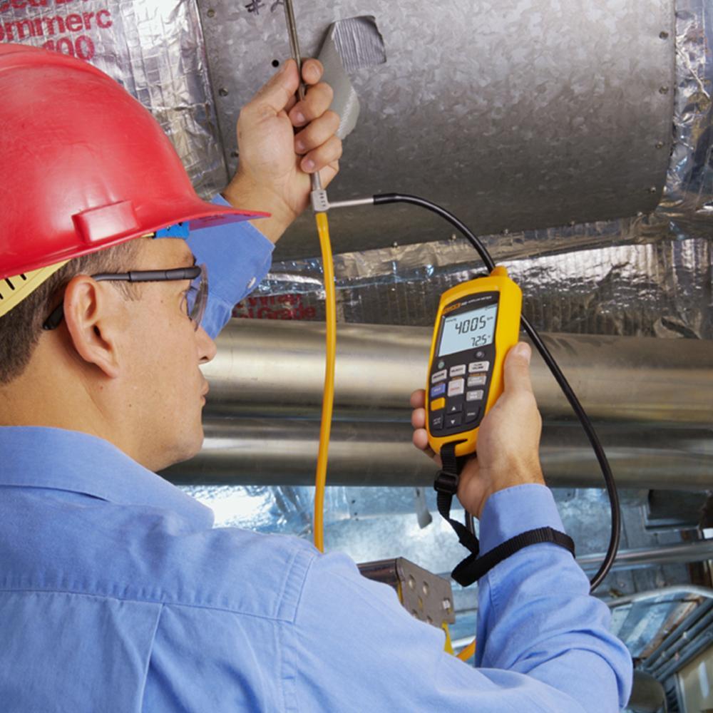
Airflow measurements can be affected by the position of the measuring instrument, turbulence, swirl, duct geometry, and the method used to calculate average velocity.
For example, measuring velocity immediately after an elbow or transition may produce an unreliable result because the airflow profile is not uniform.
A single reading taken at the center of a duct is also not necessarily representative of the average airflow across the entire cross-section.
What to check:
Confirm that the measurement instrument is suitable and calibrated.
Use an appropriate duct traverse method.
Select a measurement location with suitable flow conditions.
Record duct dimensions and calculate airflow from representative velocity measurements.
Compare readings at the fan outlet and relevant system branches where practical.
Before concluding that the fan is underperforming, verify that the airflow measurement method is appropriate for the installed duct arrangement.
10. How to Troubleshoot Low Airflow After Fan Installation
A systematic approach is more effective than changing several components at once.
The following sequence helps maintenance teams separate mechanical problems from installation and system-related problems.
| Inspection Order | What to Check | What the Result May Indicate |
|---|---|---|
| 1 | Rotation direction | Incorrect motor rotation or assembly |
| 2 | Actual fan RPM | Low speed, incorrect pulley ratio, or VFD setting |
| 3 | Inlet and outlet layout | Installation system effect |
| 4 | Dampers and filters | Excessive system resistance |
| 5 | Impeller and internal clearance | Assembly error, blockage, or damage |
| 6 | Duct joints and branches | Air leakage or poor distribution |
| 7 | Airflow and pressure measurements | Actual operating point and measurement accuracy |
For a more complete assessment, record the following values under stable operating conditions:
Airflow at the fan or relevant system branches.
Fan inlet and outlet pressure.
Fan shaft speed.
Motor current and electrical input power.
Filter differential pressure.
Damper positions.
Compare these measurements with the original fan selection data and commissioning records. Airflow alone is not enough to identify the cause of poor performance.
How to Prevent Airflow Problems Before Installation
Many post-installation airflow problems can be avoided during the design and commissioning stages.
Before ordering an industrial fan, buyers should provide the actual airflow requirement, system pressure, gas temperature, transported material, and duct arrangement. The fan should be selected for the complete system rather than for airflow capacity alone.
During installation, pay particular attention to inlet and outlet connections, fan rotation, shaft speed, internal clearances, and duct sealing.
After commissioning, record the actual operating conditions. These baseline measurements make it easier to identify future changes and determine whether a performance problem comes from the fan or the connected system.
For projects with complicated duct layouts, it is advisable to review the installation drawings with the fan manufacturer before finalizing the equipment position.
Conclusion
Fan airflow can decrease after installation because the actual site conditions differ from the conditions assumed during fan selection and testing. Common causes include excessive duct resistance, poor inlet or outlet connections, incorrect rotation, insufficient fan speed, dirty filters, installation errors, and duct leakage.
The most effective troubleshooting method is to check the fan and the complete air system together. Verify rotation and speed first, inspect the duct connections, and then compare measured airflow and pressure with the original selection data.
At Wuxi JN Fan Factory, industrial fan selection needs to consider the actual duct layout, system resistance, operating conditions, and installation requirements. Reviewing these factors before delivery and commissioning helps reduce airflow problems and supports more reliable operation after installation.