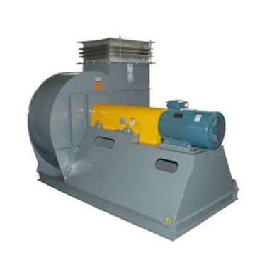
Why Is My Centrifugal Fan Not Producing Enough Airflow?
Oct 22, 2026
When a centrifugal fan cannot deliver the expected airflow, the first reaction is often to suspect that the fan is too small or that the motor does not have enough power. However, insufficient airflow does not automatically mean the fan capacity is inadequate.
A centrifugal fan can produce less air than expected because it is running at the wrong speed, rotating in the wrong direction, operating against excessive system resistance, or receiving uneven airflow at its inlet. Dirty filters, closed dampers, impeller deposits, and duct leakage can also affect the amount of air reaching the intended process.
The most important step is to determine whether the problem comes from the fan itself or from the air system connected to it. This distinction helps avoid unnecessary motor replacement, fan upgrades, and changes to the ductwork.
1. The Fan Is Rotating in the Wrong Direction
Incorrect rotation is one of the first things to check when a centrifugal fan delivers much less airflow than expected, particularly after installation, motor replacement, or electrical maintenance.
A centrifugal impeller is designed to rotate in a specific direction. If the motor connections cause it to rotate in the opposite direction, the fan may still run, but its airflow and pressure performance can be substantially reduced.
This problem is especially relevant to three-phase motors, where changing the phase sequence can reverse the direction of rotation.
Do not assume that the fan is rotating correctly simply because the motor is running normally.
How to check:
Locate the rotation arrow on the fan casing or equipment label.
Observe the impeller or shaft rotation from the specified viewing side.
Compare the actual direction with the manufacturer's instructions.
Check the motor wiring and phase sequence if the direction is incorrect.
For a three-phase motor, a qualified electrician can correct the phase sequence after isolating the power supply. The fan should then be tested again under the intended operating conditions.
2. The Fan Speed Is Lower Than the Required Speed
A centrifugal fan's airflow is closely related to its rotational speed. If the fan operates below the speed used for its original selection, it generally cannot deliver the same airflow and pressure.
Several problems can reduce the actual fan speed:
The variable frequency drive is set below the required frequency.
The motor does not reach its intended operating speed.
A belt is slipping because of wear or incorrect tension.
The motor and fan pulleys have been replaced with unsuitable sizes.
The power supply or control system is not operating as specified.
For belt-driven centrifugal fans, do not rely only on the motor nameplate speed. The fan shaft speed may be different because of the pulley ratio.
How to check: Use a suitable tachometer to measure the actual fan shaft RPM. Compare it with the selected fan specification, not just the motor's rated speed.
If the measured RPM is too low, inspect the drive arrangement and speed control before considering a larger motor.
Increasing fan speed without checking the fan's maximum permitted RPM, motor power, and mechanical limits can create additional problems.
3. Filters, Dampers, or Ducts Are Restricting Airflow
A fan may be correctly selected and operating at the intended speed but still deliver insufficient airflow because the connected system has more resistance than expected.
This is common in industrial ventilation, dust collection, and exhaust systems where filters and ductwork gradually accumulate material.
Typical restrictions include:
Dust-loaded or clogged filters.
Dampers that are partially closed.
Blocked intake grilles or protective screens.
Dust accumulation inside ductwork.
Clogged heat exchangers or process equipment.
Loose internal duct liners or other obstructions.
A replacement filter can also cause problems if its pressure drop is higher than the filter originally specified.
How to check: Inspect the filter, damper, intake, and duct sections in the direction of airflow. Where possible, measure the pressure difference across individual components.
For example, a high differential pressure across a filter indicates that the filter may be restricting airflow. If the filter pressure drop is normal but the overall system pressure is higher than expected, investigate other duct components and restrictions.
Do not remove filters permanently just to obtain a higher airflow reading. The filter may be necessary for equipment protection or process requirements.
4. The Impeller Is Dirty, Damaged, or Incorrectly Installed
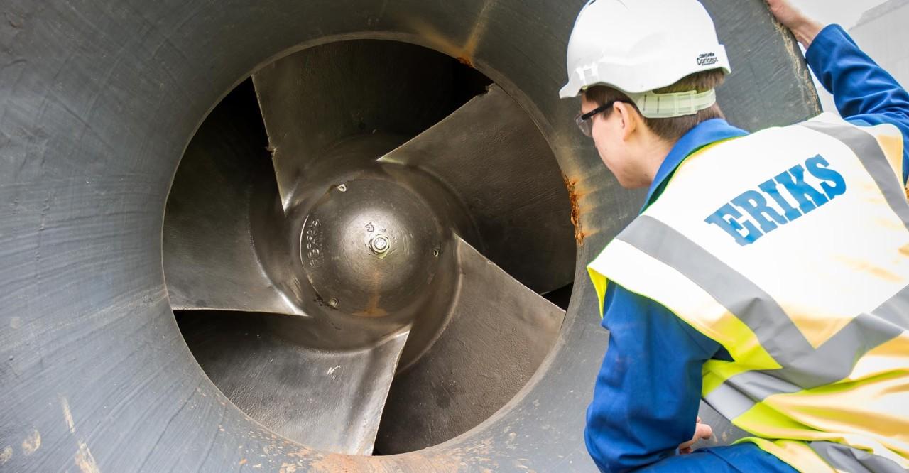
The impeller is responsible for transferring energy from the rotating shaft to the air. Its condition directly affects the fan's ability to produce the required airflow and pressure.
In industrial environments, dust, fibers, sticky particles, and process residues can accumulate on the blades and inside the impeller.
This can change the blade geometry, reduce effective flow passages, increase aerodynamic losses, and disturb the impeller's balance.
Other possible problems include:
Corroded or eroded blades.
Bent or deformed impeller blades.
Incorrect impeller installation.
An impeller mounted in the wrong orientation.
Incorrect clearance between the impeller and inlet cone.
Damage caused by foreign objects.
How to check: Isolate the fan and inspect the impeller through the designated access opening. Look for uneven deposits, blocked passages, blade deformation, and signs of contact with the casing.
If material build-up is responsible, clean the impeller using a method suitable for its material and the transported medium. If the blades are damaged or the impeller has been incorrectly assembled, consult the manufacturer before returning the fan to service.
After cleaning or repair, check the impeller's balance and running clearance as required.
5. Poor Inlet and Outlet Connections Reduce Fan Performance
A centrifugal fan does not operate independently of its ductwork. The air conditions immediately before and after the fan can have a significant effect on its actual performance.
This is known as fan system effect.
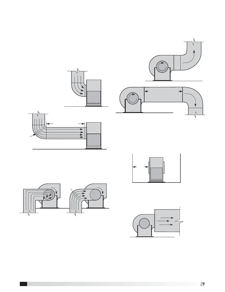
At the inlet, an elbow installed too close to the fan can create uneven airflow or swirl. Instead of entering the impeller uniformly, air reaches different parts of the wheel at different angles and velocities.
At the outlet, an abrupt duct transition or an elbow placed too close to the discharge can interfere with the airflow pattern and reduce effective pressure recovery.
Common installation problems include:
A 90-degree elbow immediately before the fan inlet.
A restrictive inlet box.
An abrupt reduction in duct size.
A discharge elbow positioned too close to the fan outlet.
Poorly arranged dampers or turning vanes.
An inlet opening installed too close to a wall or obstruction.
These conditions are not always equivalent to ordinary duct resistance. Poor inlet flow can change how the impeller operates, so simply adding a pressure-loss allowance may not accurately represent the actual performance loss.
How to check: Inspect the inlet and outlet geometry, including elbow direction, transition shape, available straight duct sections, and nearby obstructions.
Where space is limited, the solution may involve redesigning the inlet box, adding suitable turning vanes, improving the duct transition, or changing the outlet arrangement.
The exact clearance and straight-duct requirements depend on the fan model and installation configuration. Follow the manufacturer's installation instructions rather than applying one universal duct-length rule.
6. The Actual System Resistance Is Higher Than the Original Design
A centrifugal fan operates at the intersection of its fan performance curve and the system resistance curve.
If the duct system becomes more restrictive, the operating point can shift and the airflow may decrease.
This can happen even when the fan itself has not changed.
For example, an industrial exhaust system may initially operate with a certain number of extraction branches. Later, additional ducts, filters, dampers, or process equipment are added. The overall resistance may then become higher than the original design condition.
Other examples include:
Additional duct sections installed during plant expansion.
Smaller replacement ducts.
More restrictive filters or process equipment.
Dampers adjusted to serve other production areas.
Changes in the number of operating extraction points.
How to check: Compare the current duct configuration and measured static pressure with the original design information. Review whether any equipment or branches have been added, removed, or adjusted.
If the system requires more pressure than the fan was selected to provide at the target airflow, cleaning the fan alone will not solve the problem. The system may need to be redesigned, or the fan may need to be reselected for the revised duty.
7. Air Leakage Is Reducing the Air Delivered to the Required Location
Air leakage can make a fan appear to have insufficient airflow even when it is moving a substantial volume of air.
For example, in a supply ventilation system, leaks between the fan and the delivery points allow part of the air to escape before reaching the intended area.
In an exhaust system, leakage through unwanted openings can change the air distribution and reduce the amount of air captured at individual extraction points.
Common leakage locations include:
Flexible duct connections.
Flanges and gaskets.
Inspection doors.
Access panels.
Damaged duct sections.
Poorly sealed transitions.
How to check: Inspect joints and access openings for gaps, damaged seals, and loose connections. Pressure testing or suitable leakage detection methods can help locate leaks in larger systems.
Measure airflow at the actual delivery or extraction points rather than assuming that the fan outlet reading represents the air volume available at every branch.
8. The Airflow Measurement Is Not Representative
Sometimes the fan is delivering close to its intended capacity, but the measurement method gives a misleading result.
A single velocity reading at one point in a duct does not necessarily represent the average airflow across the entire duct section. Air velocity can be uneven, particularly near elbows, dampers, transitions, and fan outlets.
Other measurement problems include:
Measuring too close to a duct elbow or fan discharge.
Using an unsuitable instrument or probe.
Incorrect duct dimensions entered into the calculation.
Measuring at different operating conditions from the original test.
Comparing actual volume flow at one air density with a rating based on another condition.
Comparing airflow at the fan outlet with airflow at a downstream process point.
How to check: Use an appropriate airflow measurement method, such as a duct traverse with a suitable Pitot tube or calibrated airflow instrument. Follow the applicable measurement procedure and select a suitable measurement location.
When comparing results with the fan's rated performance, make sure the fan model, impeller, speed, air density, and pressure basis are consistent.
9. A Practical Troubleshooting Sequence for Low Centrifugal Fan Airflow
Rather than changing several components at once, use a sequence that separates fan-related problems from system-related problems.
| Check order | Inspection | What the result helps identify |
|---|---|---|
| 1 | Confirm rotation direction | Incorrect motor phase sequence or wiring |
| 2 | Measure fan shaft RPM | Low speed, belt slip, or incorrect drive ratio |
| 3 | Check filters and dampers | Local restrictions in the system |
| 4 | Inspect the impeller | Deposits, damage, incorrect installation, or clearance |
| 5 | Inspect inlet and outlet connections | Fan system effect and disturbed airflow |
| 6 | Measure airflow and static pressure | Actual operating point and system resistance |
| 7 | Check duct leakage | Loss of delivered or captured airflow |
| 8 | Compare with the fan curve | Whether the selected fan matches the current duty |
The combination of airflow and pressure readings is particularly useful.
For example:
Low airflow with high system pressure: The system may have excessive resistance, such as a clogged filter, closed damper, or restricted duct.
Low airflow with low measured pressure: Check fan speed, rotation, inlet and outlet conditions, and measurement locations. This combination can indicate a fan performance or system-effect problem.
Low airflow with abnormal motor current: Investigate the actual operating point, electrical supply, and mechanical condition rather than assuming one specific cause.
These patterns are diagnostic clues, not universal rules. Static pressure measurement locations and definitions must be consistent with the fan performance data being used.
10. When Should You Repair the Fan or Select a Different Model?
Not every low-airflow problem requires a new fan.
If the cause is a dirty impeller, slipping belt, incorrect rotation, or blocked filter, restoring the existing equipment may be sufficient.
If the fan operates correctly but the system resistance has increased because of plant modifications, the ductwork or process layout may need attention.
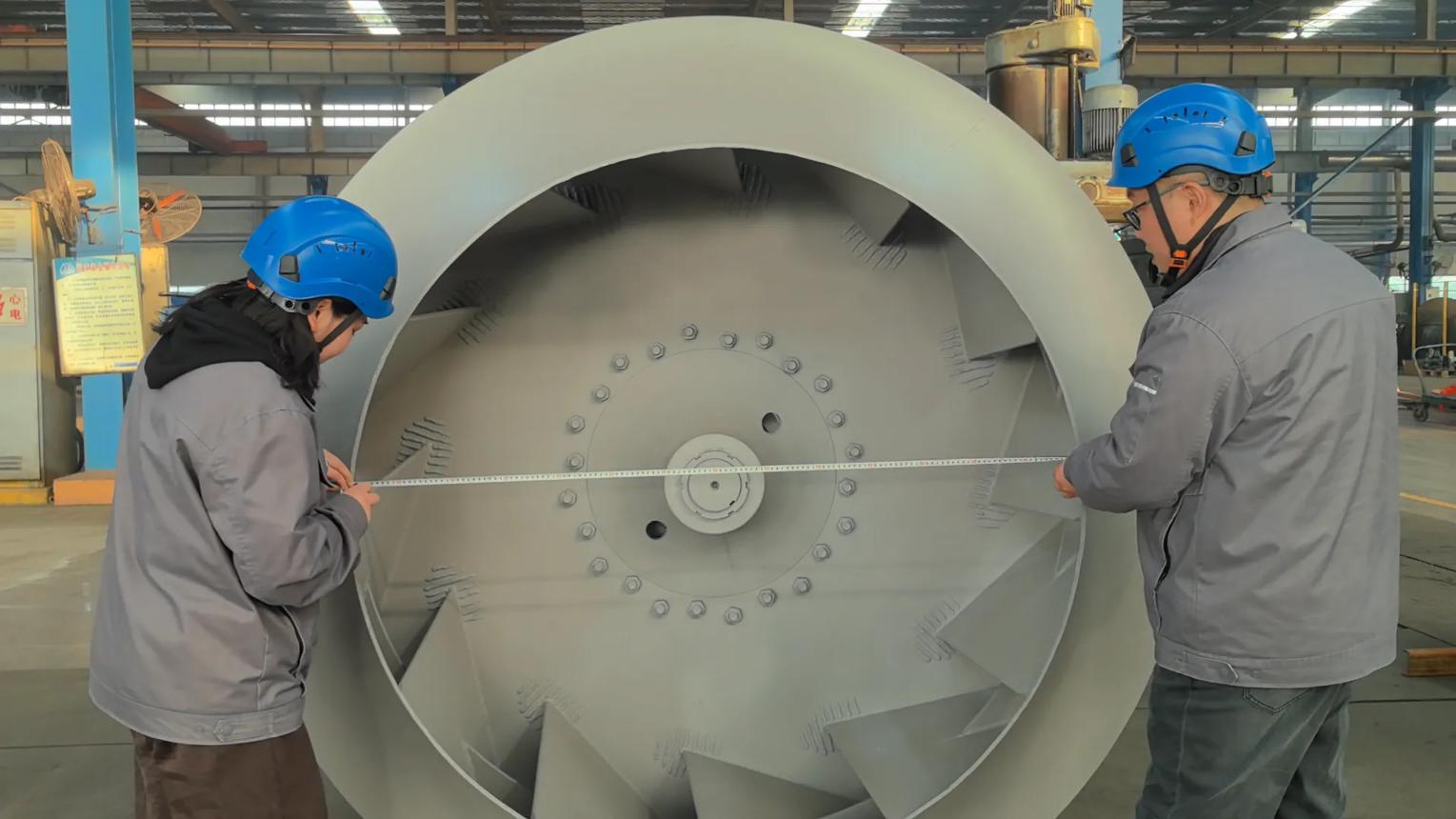
A different fan selection becomes worth considering when the required airflow and pressure have changed permanently, or when the existing fan cannot meet the revised operating conditions within its permitted speed and power range.
Before selecting a replacement, confirm:
Required airflow at the actual operating condition.
Required static or total pressure, using a consistent pressure definition.
Duct layout and component pressure losses.
Air temperature, density, and transported material.
Continuous operating requirements.
Available motor power and permitted fan speed.
A replacement fan should be selected for the actual system duty, not simply by choosing a larger motor or a model with a higher nominal airflow figure.
Conclusion
When a centrifugal fan does not produce enough airflow, the problem may come from incorrect rotation, low fan speed, restricted ducts, impeller contamination, poor inlet and outlet connections, increased system resistance, or air leakage.
The most reliable approach is to check the fan and the connected system separately, then compare measured airflow and pressure with the fan's performance curve.
For industrial ventilation, dust collection, and exhaust applications, correct fan selection depends on more than the airflow figure alone. The required pressure, duct arrangement, operating conditions, and installation details all affect whether the fan can deliver the expected performance.
At Wuxi JN Fan Factory, centrifugal fan selection should be based on the actual airflow and pressure requirements of the application. Providing the duct layout, transported medium, operating temperature, and required duty point helps determine a suitable fan configuration for the system.